Dual Cree Bicycle Headlight
 You can build your own bike light with easy-to-order parts, and it'll
cost less than commercial lights that are not as bright and don't have
as many features. My light has five different output levels, regulated
current, two levels of low-voltage warnings, overheating protection,
three hour runtime at maximum power, and 30 minute recharge time.
Most of this comes from the bFlex driver from
TaskLED
that I use. It provides all those features in one very configurable
package.
You can build your own bike light with easy-to-order parts, and it'll
cost less than commercial lights that are not as bright and don't have
as many features. My light has five different output levels, regulated
current, two levels of low-voltage warnings, overheating protection,
three hour runtime at maximum power, and 30 minute recharge time.
Most of this comes from the bFlex driver from
TaskLED
that I use. It provides all those features in one very configurable
package.
It's also made possible by using the newest LED technology. LEDs have just
recently surpassed all other light sources (including flourescent) in
terms of efficiency.
My light is probably brighter than any mainstream commercially available
headlights of similar power (and much higher cost), even commercial LED
headlights. Commercial vendors
have to lock in one part and use that part for months, whereas you can
order the newest brightest LEDs -- and this market is changing rapidly. For
comparison, the 5W vistalite, which uses a halogen lightbulb puts out
light that would fall between my light's lowest two levels (and my light
consumes 0.6W and 1.3W at those two light levels. At it's brightest,
I'm probably about 1/3 as bright as a car headlight, and should have a
runtime of almost three hours.
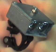
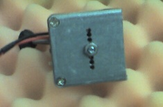
 I made my case from a hammond 1590G, cut in half (enough left over for
another light head!). I hand-carved an aluminum heat sink to fit the case,
with holes drilled through top to bottom for cooling, and a center hole
for a mounting bolt. This bolt also serves as an additional bolt for
closing the box, as it would only have two screws at one end after being
cut in half. It will thread through a vistalight mounting bracket on the
bottom. The case has matching cooling holes top and bottom.
I made my case from a hammond 1590G, cut in half (enough left over for
another light head!). I hand-carved an aluminum heat sink to fit the case,
with holes drilled through top to bottom for cooling, and a center hole
for a mounting bolt. This bolt also serves as an additional bolt for
closing the box, as it would only have two screws at one end after being
cut in half. It will thread through a vistalight mounting bracket on the
bottom. The case has matching cooling holes top and bottom.
I'll be gluing the heat sink into the bottom half with thermal epoxy,
and sealing the lid on with silicone. I could have (should have) ordered
the 1590WG which has a waterproof liner on the lid, and would have reduced
the amount of sealing I need to do.
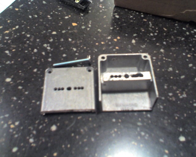
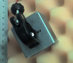
I tried to turn the the drilled thru-holes into a channel, and it didn't
go well (I was trying to cut too much at once), so I didn't try it on the
other side.
As it turns out, the inside dimension of the case is 1.6 mm shorter than the
Ledil optics I'll be using. I've trimmed the optics down just a bit to fit.
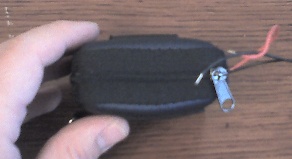
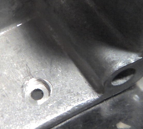 There's also a hole for the tiny NKK illuminated switch I'm using. The
hole is 2 mm diameter. The recessed area will let me glue in and seal
the plastic switch bushing,
which is 4mm diameter. The remaining wall thickness here is about 0.6 mm.
There's also a hole for the tiny NKK illuminated switch I'm using. The
hole is 2 mm diameter. The recessed area will let me glue in and seal
the plastic switch bushing,
which is 4mm diameter. The remaining wall thickness here is about 0.6 mm.
You can see this hole in the (blurry) picture above of the case, in the
back on the left side.
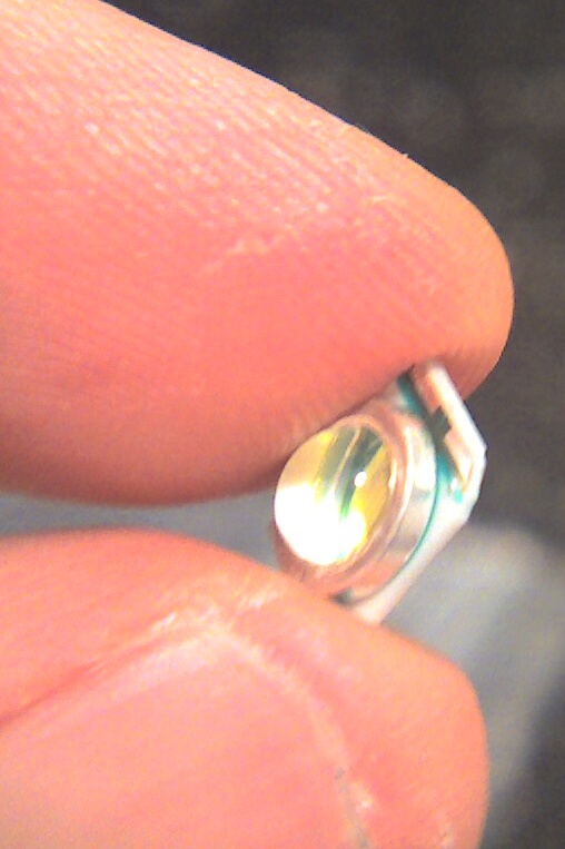
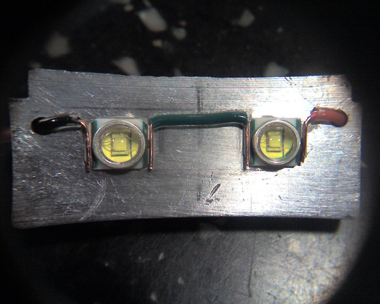
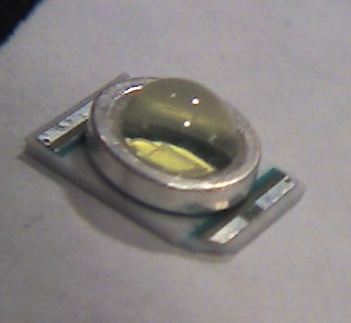 These Cree leds are much smaller than you think they are from seeing blown
up pictures.
These Cree leds are much smaller than you think they are from seeing blown
up pictures.
These pictures were taken after making the first
corner cut. This is necessary because the led has little copper vias at
each corner to connect the upper pads to the lower pads, and the Arctic
Silver thermal adhesive I'm using is somewhat capacitive. I could probably
have skipped it but I'm paranoid. I could also have used Arctic Alumina
thermal epoxy but it's only about half as heat-conductive as the Silver.
I could also have scraped off the bottom tracks, but the copper vias would
still be exposed, and again, I'm paranoid.
Snipping the corners with wire cutters turned out to be quick and easy, and
did not shatter the boards. If you cut right at the dots on the corners,
you'll probably expose the via without cutting it off, so go just slightly
past them.
Only work on these things if you have magnification. I had a head-mounted
lupe that I was using. I also used it to take the closeup pictures here,
by holding the lupe up to the cell-phone lens.
 Click for a larger image.
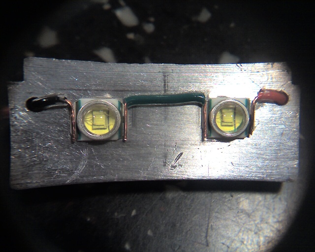
This is the heat sink, after gluing on the LEDs. I've also formed the wires
and put them in place, but they have not been soldered yet. Gluing was
done with the thinnest layer of epoxy possible. The ledil optics were
held in place over the LEDs, to get the position right, until the epoxy
was holding them. Careful not to glue the optics to the heat sink!
The heat sink looks to be a funny shape because of the pincushion introduced
by using a cell phone and a lupe to take the picutre. I did get the
focus just right on this one, so it looks good enlarged.
I'm using 24-gauge solid copper wire. Actually, I had some radio shack
intercom wire with red, green, black, and white joined together in a strip,
so I used that. If the insulation looks oddly thick, or transparent on
the surface, that's why.
 Click for a larger image.
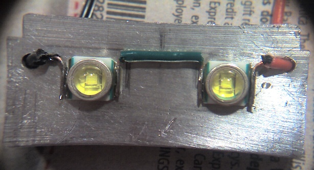
And here after soldering.
Gluing first was a terrifically great idea. I have no idea how I could have
held everything in place otherwise. The heatsink made everything stable.
I used a pair of vise grips to hold the heat sink, just to make everything
that much more stable.
First, I tinned the wire leads, and
also the solder pads on the leds. I taped all the wires in place (with
painter's blue tape) for soldering. I made sure that the wire leads were
perfectly placed to be in contact with the pads for the full length of the
pad. I added a tiny bit of flux to everything
with a toothpick. Then a couple of seconds with the soldering iron got
everything to flow together. I had to redo one joint because the wire had
come up on one end when I soldered it.
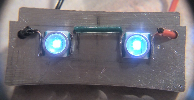
And here, with a minimal circuit test. I hooked the two leds up to four
partially charged NiMH cells, so about 4.8 volts. In real life, this was
even more feeble, and you could see a grid of illuminated lines inside
the led dome.
 Click for a larger image.
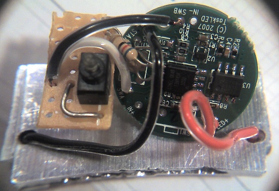
Now I've soldered on the bFlex, and also soldered the illuminated pushbutton
onto the bFlex. The pushbutton gets it's own board made from a standard
radio shack PC board. The black wire going to SWB doubles as the ground
for the LED, hence that jumper wire. On the other side of the LED I
needed about 30 ohms, but hadn't (correctly) calculated that initially and
didn't have the right value on hand, so I used two 62 ohms in parallel.
FYI, the bFlex puts out 2.5V for the status led, expected to drive at
20 mA. The NKK switch optimally wants 1.9V at 20 mA. so R = (2.5-1.9)/0.02
= 30 ohms.
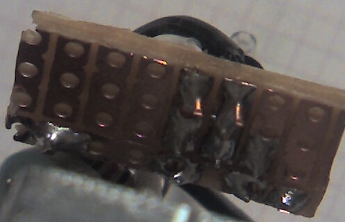
A closeup of the backside of the pushbutton board. Someday I'll learn to
solder.
 Click for a larger image.
Here the same assembly is in the case, with the pushbutton more or less
in place. The bFlex will stay at that odd angle, because it's too tall to
stand upright inside the case.
I need something to brace the pushbutton board in place so that
when I push against the button it pushes against the heat sink (which will
be glued into the case with thermal epoxy). Two layers of corrugated
cardboard should do the trick.
 Click for a larger image.
This is what the button looks like when it's in it's hole.
You might notice that I forgot to drill the holes for the battery
cables, so work stops until I can find the time to do that (I live in an
condo building, and can't really drill late at night).
So I have drilled the holes for power now, and hooked up my battery
pack. Everything is soldered together and it all works. YAY!
I need some pictures of the assembled inside of the light. Maybe I'll get
to that someday. The parts are a very tight fit inside, all bunched up
wires. Where the
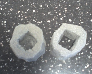
 One of my battery holders fits inside a water bottle (the 2x2x2 holder).
But since I don't want it to rattle around, I cut a couple of foam spacers
to keep it softly in place inside the water bottle.
The batteries fit nice and snug.
One of my battery holders fits inside a water bottle (the 2x2x2 holder).
But since I don't want it to rattle around, I cut a couple of foam spacers
to keep it softly in place inside the water bottle.
The batteries fit nice and snug.
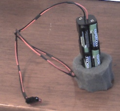
I don't have a clear picture, but this battery holder happened to have
two holes at either end, and the wires fit through perfectly. So for
the purposes of strain relief, the wires go through the battery, come out
at the terminal end, are tied in a UL knot, and then soldered. I could
probably swing this thing around my head with batteries loaded, and not
hurt the solder joints at all.
 And the bottle is ready. The whole through the foam has just enough
clearance that the battery holder slides in and out with only a little
resistance, but it's still held comfortably in place.
And the bottle is ready. The whole through the foam has just enough
clearance that the battery holder slides in and out with only a little
resistance, but it's still held comfortably in place.
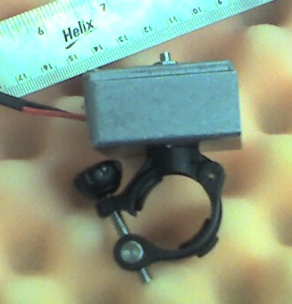
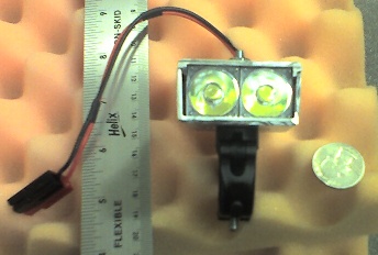
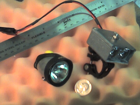 Here's the final assembled light. The handlebar bracket comes from the
Vistalight, which is also pictured here for scale. This is a pretty
small light.
Here's the final assembled light. The handlebar bracket comes from the
Vistalight, which is also pictured here for scale. This is a pretty
small light.
The bottom of a vistalite has a couple of raised metal spots which fit
inside a plastic piece in the handlebar bracket. This keeps the
screw from tightening or loosening when you swivel the headlight. I
could add this feature to my light, but so far, it doesn't look like
it will be a problem, so I'm not bothering.
You can see the influence of the bikecurrent mailing list, where the
advocated for using a pigtail instead of a barrel connector. The
connectors are are AMP powerlock, which are Anderson Powerpole knockoffs.
I managed to crimp them with the crappy crimper/stripper tool that is
everybody's first crimper/stripper. But I also soldered them. Note
that once you slide the read and black (or colors of your choosing)
AMP powerlock connectors together next to each other, they don't come
undone without breaking a little plastic doohickey. This is not a big
deal if you simply got the sides wrong, because then you just use the
other unbroken side.
Might as well mention here that the other end of the pigtail has a
UL knot inside the case before it's soldered, so it should be nicely
strain-relieved.
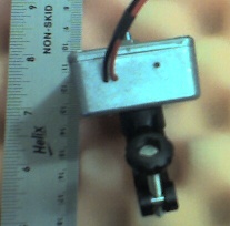
You'll notice on the picture of the underside that the handlebar bracket
actually covers a couple of the ventilation holes. The holes are all
connected on the inside, so things should still be fine.
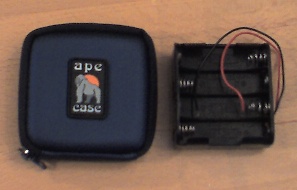
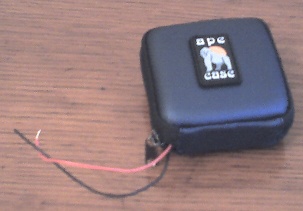
I have another battery holder in the works. The battery holder used here
is the more typical 2x4 configuration. I found this great Ape Case at
Microcenter that's designed to hold four batteries and some flash cards.
It's a tight squeeze, but I can get this battery holder inside and have
a great battery pack that's easy to open to change the batteries, and
even marginally water resistant without a ziplock. It's got a belt loop
on it, which I'll use to add a velcro strap to velcro this wherever I need
it.
Summary
The bFlex is fabulous. I love it. I have the UIB2 interface, and I've
got it configured for 5 light levels to a maximum of 1000 mA. The light
levels are all distincly different from one another. And I'll guess that
the dimmest one is almost as bright as a 5W Vistalite (I'll actually test
this if I can get the Vistalite to work again). Here's
the measured voltages for the five different light levels:
L1=5.8V, L2=6.3V, L3=6.6V, L4=7V, L5=7.5V.
Assuming 8 2650 mAh batteries (which is what I bought),
and 88% efficiency, this is my expected run time at the light levels
that the bFlex produces:
| mA | V | W | lm | battery A | t (hours) |
| 100 | 5.8 | 0.6 | 80 | 0.07 | 38:35 |
| 200 | 6.3 | 1.3 | 150 | 0.15 | 17:46 |
| 350 | 6.6 | 2.3 | 214 | 0.27 | 9:41 |
| 700 | 7.0 | 4.9 | 340 | 0.58 | 4:34 |
| 1000 | 7.5 | 7.5 | 440 | 0.89 | 2:59 |
The LED voltage to current for the last three comes straight from the data
sheet. The current for the two lower voltages was roughly estimated from
a graph in the Cree datasheet. The lumens are also estimated from a graph.
In practice however, eight cells cuts it close on regulation. As the
battery pack voltage drops, the bflex no longer has enough cushion to keep
the light in regulation. With fresh batteries that measured over 11V,
I powered the light at full power. Initially that battery voltage with load
was 10.76V. After an hour, this had dropped to 9.86V. I think things will
go out of regulation around 1 to 1.5 volts above the load, so around 8.5 to
9 volts. At this point the battery still has lots of juice left in it,
just not enough for full power. That's a good argument for a 12-cell
pack, which should stay in regulation until the pack is drained.
In theory, I can hook up any battery pack that's over 8.5 volts (9 volts is
probably more ideal). I could hook up 16 cells for longer run time. Or
3 Lithium cells should be enough to run it (four would be a safer bet for
the same reason that 8 NiMH cells cut it close).
Indoors, this light gets HOT. Hot enough to shrink some heatshrink that I
used inside the case to shield the bflex from the aluminum case.
Hot enough to burn my fingers if I hold it
too long. Outside in the cold, with wind from riding a bike, it isn't a
problem. I'm not sure how it will work out in the summer nights. But
I'll be using the temperature limit option in the bFlex. If I had it to do
over, I'd seriously consider my custom heat sink in a plastic case. Then
the entire case wouldn't get so hot. I think I'd add fins to the heat
sink top and/or bottom since I wouldn't have the case to distribute the heat.
Parts List
| Part | Qty | @Price | From | Notes |
|---|
| bFlex | 1 | $30 | TaskLED |
I got the UIB2 interface, and I love it. This is the most expensive part
of the light (except the charger), but I see no reason to skimp. For
$20 or so I could get a
dumb driver, and then I'd have to add a bunch of stuff to get different
light levels, and I wouldn't have low voltage warnings, and I wouldn't have
a temperature sensor. Worth every penny.
|
| CREE XR-E Q5 WC | 2 | $15 | Cutter |
The Q5 bin was the brightest at time of purchase. The brighter R bins
should be out soon. The WC tint was
recommended on CandlePowerForums (CPF) as a good one. It was more expensive
than other tints, but what the hack. It's somewhat bluish, and I'm happy
with it, but maybe I'd have
been just as happy with Q5 in another tint and eight more bucks in my wallet?
Another choice is to get this in a star configuration. In other words, the
emitter comes pre-soldered to a hexagonal (or "star"-shaped) circuit board
that supposedly transfers heat well, and has no electrically active contacts
on the bottom. You don't get as
good of a heatsink connection, but you also don't have to trim the corners
of the emitter
or do such delicate soldering. But the trimming and soldering went pretty
well for me. Also, a discussion on CPF indicated that some of these
that are available as "stars" are not well-soldered and don't really transfer
heat so well.
Then again the LED will be obsolete in a year so who cares if it isn't heat
sinked so well?
|
| Ledil CRS-RS | 2 | $3.95 | Cutter |
This is their narrowest-beam optic. For on-road riding that's the
way to go, IMHO. They still spread a lot of light around. I chose these
optics based on low price and small size, and square shape.
|
| Hammond 1590WG | 1 | $7.88 | Mouser |
I could actually make two lightheads from this one case, so the quantity
should probably be 1/2.
Case selection (together with optics selection) can go in a million
different directions. This is what I settled on, because it would hold
the optics more or less ok, and have room left for all the rest.
I had a grander
scheme for making my own case, but I had to settle with making my own
heatsink instead.
|
| Aluminum heatsink | 1 | free | homemade |
I got some scrap aluminum from a machine shop, and spent several hours
carving the heat sink. An easier route would be to get some copper around
an eight or sixteenth of an inch thick, and cut and bend it into shape
as a heat sink, and glue it to the case (and forgot about my fancy vent
holes).
|
| Arctic Silver Thermal Adhesive | 1 | $10.00 | Microcenter |
Used to glue the emitters to the heatsink, and the heatsink to the case.
You get two tubes to mix, and you need very little of it.
If you don't want to worry about conductivity (and having to breaking the
connection to the bottom contacts on the Cree emitters) then use Arctic
Alumina Thermal Adhesive, which is not electrically conductive (and
only about half as heat-conductive).
|
| NKK GB15JPD | 1 | $5.60 | Mouser |
This is the tiniest illuminated push-button I could find. It's washable,
but it doesn't have a specific IP rating, but hopefully it will be water
resistant enough for my needs.
An illuminated switch is not required; you could use a separate switch and
led, or you could skip the led entirely as the bFlex will flash the
main light when battery voltage drops too low. If you don't go with an
illuminated switch, there's tons of choices.
|
| 30 ohm resistor | 1 | $0.10 | Mouser |
Obviously, if you use a different status indicator you'll probably need
a different resistor value. 27 or 33 are more standard values and either
should be fine (27 will be slightly brighter than 33). I actually used
two 62 ohms, because I calculated wrong. Resistors are cheap, just order
a bunch of different ones.
If you don't use the status indicator you won't need any resistors.
|
| PC board | 1 | $3 | Radio Shack |
Don't remember the exact price. I got a small one that has lots of
groups of three holes tracked together, with some longer tracks running
up and down the length of the board. You only need a little piece of
it, and could make a dozen more pushbutton boards from it.
|
| 8xAA Battery Holder | 1 | $1.38 | Mouser |
A standard 2x4 battery holder, available wherever you order.
I already owned the other battery holder (from Radio Shack long ago)
that holds the batteries in 2x2x2, and fits in a water bottle.
You want to order something that's easy to connect to. I almost ruined
my old 2x2x2 by soldering directly to the terminals, which melted the
plastic a bit.
|
| Ape Case Media and Battery Case | 1 | $8.99 | Microcenter |
I used this to hold the battery holder, make it somewhat water resistant.
It's a very tight fit. If the stitching pops open I'll let you know.
Water resistance can be improved with a ZipLock snack bag around the holder
but inside the case.
|
| AMP Powerlock connectors | 4 or more | $1.98 | Mouser |
These are knock-offs of the more expensive and less available Anderson
powerpole connectors. It's actually three seperate parts: the crimp
contacts (AMP 53892-4) for 0.38, the red housings (AMP 53894-4) for 0.83,
and the black housings (AMP 53894-2) for
0.77. You need at least four - a red and a black on the battery, and
a red and a black on the light. If you want other battery options, order
more. Also, order extra crimp contacts in case you botch things up.
There's a massively large variety of choices available for power connection.
These (the Andersons actually) were recommended on the bikecurrent mailing
list.
You could also skip them entirely and hard wire your batteries to your light.
|
| 24-gauge wire | not very much | free | already owned |
Used for all the interior wiring. I already had a spool of Radio Shack
intercom wire, which is like a four wire (and four color) zip cord. Although
it doesn't really unzip so well, but I got it to work. The clear covering
that joined the four different wires is why my interior wiring looks so
thick.
|
| 18-gauge wire | as needed | $5.99 | Radio Shack |
I bought three 15-foot rolls in red,black,green, which is more than I need,
used for the battery cords.
|
| 8x32 1-1/2" bolt/nut/lockwasher | 1 | 0.50 | Ace Hardware |
Stainless. Don't really remember the price but it musta been less than fifty
cents.
|
| handlebar mounting | 1 | free | already owned |
From an old Vistalite 5W bike light
|
| Sealant | 1 | ? | ? |
Haven't bought anything yet. I need something that won't mess up
plastic and isn't conductive. Some (but not all) silicone sealants
will fit the bill.
|
| 15 Minute Battery Charger | 1 | $39.99 | Staples |
This is a four-position charger. So I can recharge my eight-cell pack in 30
minutes (or less, if not full emptied). Note that you can get much cheaper
(and slower) chargers. Also, this came with four 2400 mAh batteries, that
I am not using, and you don't have to be as ridiculously married to
maximizing your capacity as I am.
|
| Duracell 2650 mAh AA batteries | 8 | 4@$10 | Staples |
The highest capaciy NiMH AA batteries I could find.
|
| XXX | XXX | XXX | XXX |
XXX
|
You can do the math, but it comes in somewhere around $180, which is
a little cheaper than commercial dual led lights, and this should
be brighter than those, and is all-around better (brightness, run
time, light levels, low-battery warnings, overheating, charge time).
Also, I really pushed the price up with my $40 charger, which is not
at all necessary.
But be aware that there will be additional cost in tools:
soldering iron, solder, flux, wire cutters, wire stripper, crimpers,
magnifying glass, saw, drill, drill bits, and more. If you've already
got stuff lying around (tools, batteries, charger), and you're frugal,
you can probably get this
down close to $100. On the other hand, if you need all new tools, you
could easily spend more than a new commercial light.
Also a large
amount of time. At least twenty hours, realistically fifty or more.
Most of your time will go into designing and building the packaging
for your light.
How I carved the heatsink
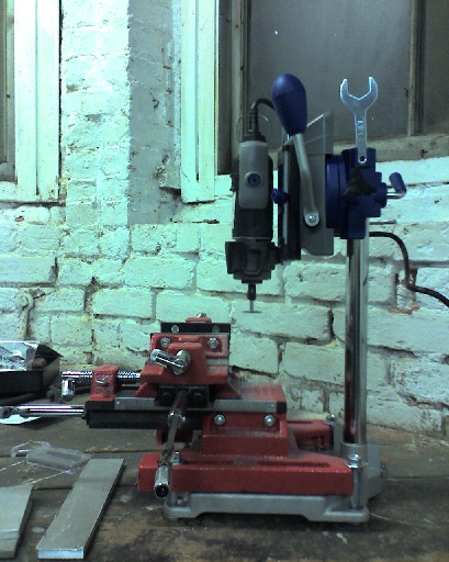
 I combined a Rockler Machinist's Vise with a Dremel workstation to create
my own mini-milling machine. It's pretty crappy as a mill. The dremel
workstation has a lot of flex in it. The tool itself has poor clearance
when trying to work inside a small metal box. It has very little reach
from the riser too, so half of the front-to-back motion in the vise was
not useable. And the riser could rise higher, especially with six inches
of vise underneath it.
I combined a Rockler Machinist's Vise with a Dremel workstation to create
my own mini-milling machine. It's pretty crappy as a mill. The dremel
workstation has a lot of flex in it. The tool itself has poor clearance
when trying to work inside a small metal box. It has very little reach
from the riser too, so half of the front-to-back motion in the vise was
not useable. And the riser could rise higher, especially with six inches
of vise underneath it.
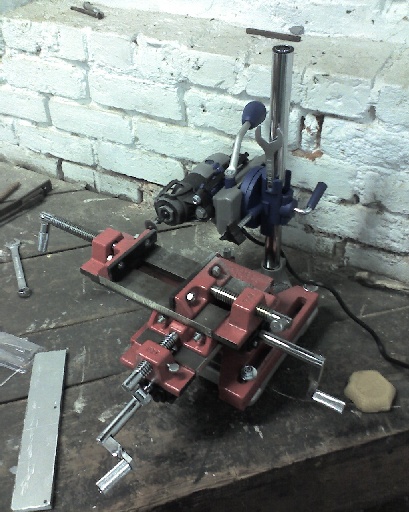
The rockler vise is nice. You can adjust for tighter,
harder, more accurate action, or looser, floppier, faster action. Even at
it's best adjustment, there's still some slop, and an eighth turn of backlash,
but most of the errors I get come from the stand and the tool, not from the
vise.
But, as crappy as it is, it lets me do things both more accurately and more
quickly than I could without it. Without the vise, I could probably
do things fairly accurately, but setup times would be significant, especially
things like drilling multiple holes in a row, or machining a smooth edge.
The limited reach and clearance of the dremel makes it hard to mount things
and make some cuts, but on the other hand,
the dremel workstation lets you orient the dremel in different ways, which
helps this problem somewhat.
 Click for a larger image.
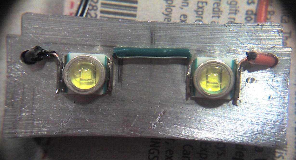 Click for a larger image.
 Click for a larger image.
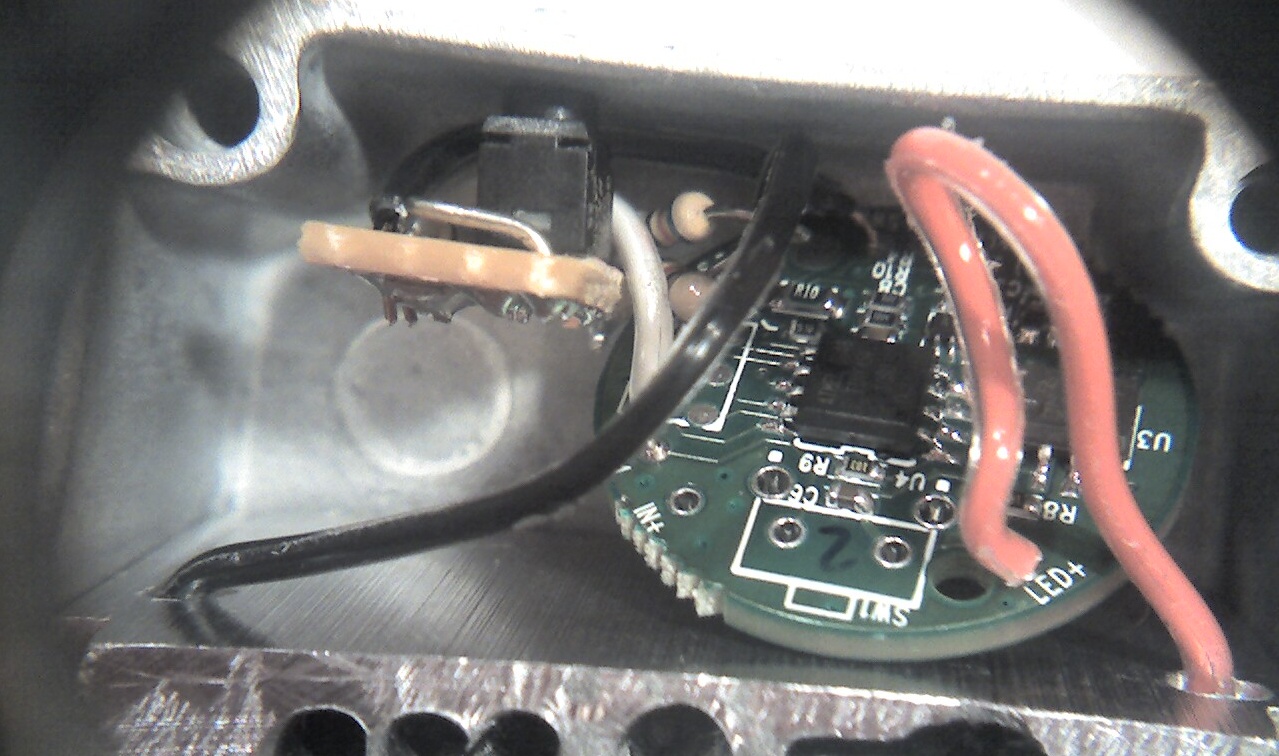 Click for a larger image.
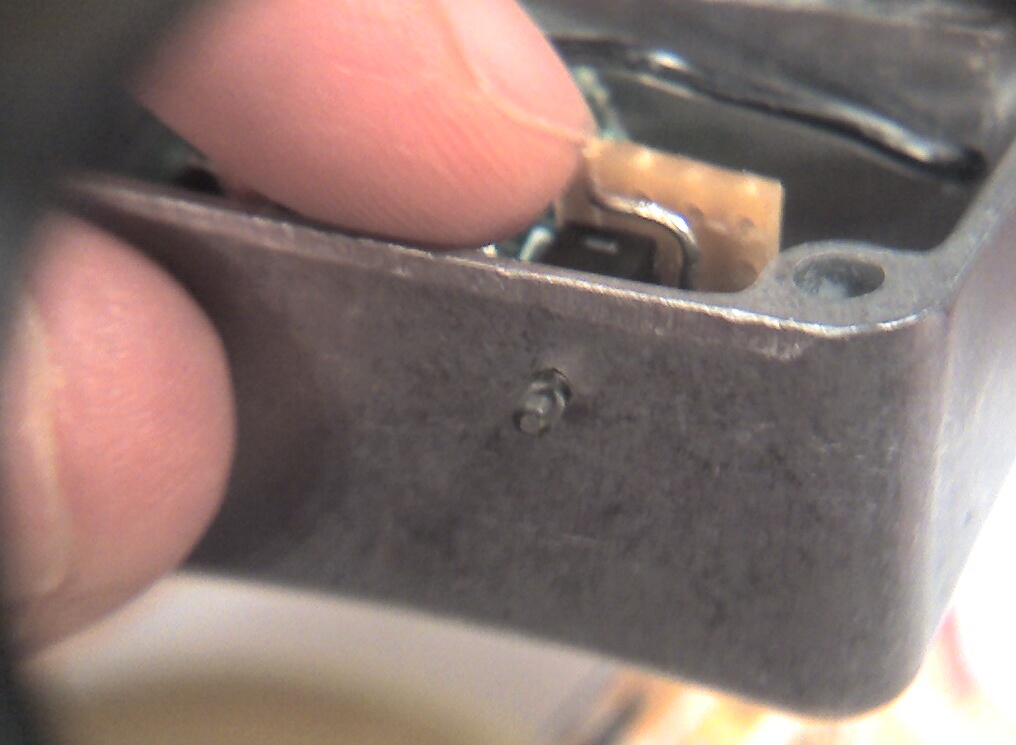 Click for a larger image.